Sunday, September 23, 2007

IC Packaging

The heart of all electronics is the active device, and the ubiquitous active device is the transistor. Virtually all real progress in electronics accures from improvement of the basic device and enabling the use of more and more of them within constraints of size, weight, cost, and energy consumption.

In order for the active device to function, it must be electrically connected to other devices-with physical assurance that the connections will be maintained. Further, the active device must be protected from attack by the environment. Finally, since the active device consumes power to perform its function, heat is generated. Since heat can shorten the life of active devices, a means must be provided to carry the heat away.

To provide these necessary functions of interconnection, physical support, environmental protection and heat dissipation, the active device must be surrounded by or encased in a package. An illustrarion of this concept is presented in Figure 1. Packages may be simple or they maybe complex-depending on the nature of the device, the system of which it is a part and the environment in which the device must operate.

The very surrounding of the active device with protective material, however, can degrade the performance if the device, increase its physical size and weight, make testing the device more difficult and decrease reliability. Moreover, the art of
making the electronic package incure costs-which may be far higher than the cost of the active device itself. Thus, the art of providing an effective electronic package becomes a complex balence of providing desired functions against constraints which may interact among themselves as even further constraints.

As a practical matter, the IC manufacturer must decide whether to package a given IC in one or more standard packages (nesessary for merchant sales) or develop one unique to its needs (giving it a systems advantage over its competitors). We will confine our discusions to "standard" types, however.

Sunday, September 16, 2007

What is wire bonding

Wire bonding is a method of making interconnections between a microchip and other electronics as part of semiconductor device fabrication.

The wire is generally made up of one of the following:

Wire diameters start at 15 µm and can be up to several hundred micrometres for high-powered applications.

There are two main classes of wire bonding:

Ball bonding usually is restricted to gold and copper wire and usually requires heat. Wedge bonding can use either gold or aluminium wire, with only the gold wire requiring heat.

In either type of wire bonding, the wire is attached at both ends using some combination of heat, pressure, and ultrasonic energy to make a weld.

Wire bonding is generally considered the most cost-effective and flexible interconnect technology, and is used to assemble the vast majority of semiconductor packages.

Category: Sem

Tuesday, September 11, 2007

What is Flip Chip

What is Flip Chip?

Flip Chip (FC) is not a specific package (like SOIC), or even a package type (like BGA). Flip Chip describes the method of electrically connecting the die to the package carrier. The package carrier, either substrate or leadframe, then provides the connection from the die to the exterior of the package. In "standard" packaging, the interconnection between the die and the carrier is made using wire. The die is attached to the carrier face up, then a wire is bonded first to the die, then looped and bonded to the carrier. Wires are typically 1-5 mm in length, and 25-35 µm in diameter. In contrast, the interconnection between the die and carrier in flip chip packaging is made through a conductive "bump" that is placed directly on the die surface. The bumped die is then "flipped over" and placed face down, with the bumps connecting to the carrier directly. A bump is typically 70-100 µm high, and 100-125 µm in diameter.

The flip chip connection is generally formed one of two ways: using solder or using conductive adhesive. By far, the most common packaging interconnect is solder Current solder types are: eutectic (63%Sn, 37%Pb) or high lead (95%Pb, 5%Sn) or lead-free (97.5%Sn, 2.5%Ag) compositions. The solder bumped die is attached to a substrate by a solder reflow process, very similar to the process used to attach BGA balls to the package exterior. After the die is soldered, underfill is added between the die and the substrate. Underfill is a specially engineered epoxy that fills the area between the die and the carrier, surrounding the solder bumps. It is designed to control the stress in the solder joints caused by the difference in thermal expansion between the silicon die and the carrier. Once cured, the underfill absorbs the stress, reducing the strain on the solder bumps, greatly increasing the life of the finished package. The chip attach and underfill steps are the basics of flip chip interconnect. Beyond this, the remainder of package construction surrounding the die can take many forms and can generally utilize existing manufacturing processes and package formats.

flipchip Wirebond CABGA Cross Section Drawing


flipchip CABGA Cross Section Drawing

Benefits of Flip Chip:

Using flip chip interconnect offers a number of possible advantages to the user:

  • Reduced signal inductance - because the interconnect is MUCH shorter in length (0.1 mm vs 1-5 mm), the inductance of the signal path is greatly reduced. This is a key factor in high speed communication and switching devices.

  • Reduced power/ground inductance - by using flip chip interconnect, power can be brought directly into the core of the die, rather than having to be routed to the edges. This greatly decreases the noise of the core power, improving performance of the silicon.

  • Higher signal density - the entire surface of the die can be used for interconnect, rather than just the edges. This is similar to the com parison between QFP and BGA packages. Because flip chip can connect over the surface of the die, it can support vastly larger numbers of interconnects on the same die size.

  • Die shrink - for pad limited die (die where size is determined by the edge space required for bond pads), the size of the die can be reduced, saving silicon cost.

  • Reduced package footprint - in some cases, the total package size can be reduced using flip chip. This can be achieved by either reducing the die to package edge requirements, since you no longer have to leave space for wires, or in utilizing higher density sub strate technology, which allows for reduced package pitch
  • Saturday, March 17, 2007

    Single Element Semiconductors


    Silicon, Si - the most common semiconductor, atomic number 14, energy gap Eg = 1.12 eV - indirect bandgap; crystal structure - diamond, lattice constant 0.543 nm, atomic concentration 5x10²² atoms/cm-3, index of refraction 3.42, density 2.33 g/cm3, dielectric constant 11.7, intrinsic carrier concentration 1.02 x 1010 cm-3, mobility of electrons and holes at 300 K: 1450 and 500 cm2/V-s, thermal conductivity 1.31 W/cm-oC, thermal expansion coefficient 2.6 x 10⁻⁶ 1/oC, melting point 1414 oC; excellent mechanical properties (MEMS applications); single crystal Si can be processed into wafers up to 300 mm in diameter.
    Ge, C, Sb.

    Silicon on Insulator (SOI)

    Only a thin layer on the surface of a silicon wafer is used for making electronic components; the rest serves essentially as a mechanical support. The role of SOI is to electronically insulate a fine layer of monocrystalline silicon from the rest of the silicon wafer. Integrated circuits can then be fabricated on the top layer of the SOI wafers using the same processes as would be used on plain silicon wafers. The embedded layer of insulation enables the SOI-based chips to function at significantly higher speeds while reducing electrical losses. The result is an increase in performance and a reduction in power consumption. There are two types of SOI wafers. Thin film SOI wafers have a device layer <1.5>1.5 ?m.
    Wafer bonding. - In this process the surface of two wafers are coated with an insulating layer (usually oxide). The insulating layers are then bonded together in a furnace creating one single wafer with a buried oxide layer (BOX) sandwiched between layers of semiconductor. The top of the wafer is then lapped and polished until a desired thickness of semiconductor above the BOX is achieved.
    SIMOX - Seperation by Implantation of Oxide. In this process a bulk semiconductor wafer is bombarded with oxygen ions, crating a layer of buried oxide. The thickness of intrinsic semiconducor above the box is determined by the ion energy. An anneal reinforces Si-O bonds in the BOX.
    Smart Cut - The wafer bonding method is used to form the BOX, but instead of lapping off excess semiconducor (which is wasteful) a layer of hydrogen is implanted to a depth specifying the desired active layer of semiconductor. An anneal at ~500oC splits the wafer along the stress plane created by the implanted hydrogen. The split wafer may then be reused to form other SIO wafers.


    Monday, February 19, 2007

    Semiconductor Packaging Goes Vertical

    Stacked packaging gets more silicon in less space
    Randy Frank, Contributing Editor -- Design News, June 5, 2006

    When Nokia and Amkor Technology discussed 3D packaging roadmaps five years ago, the stage was set for a new packaging solution for logic plus memory integration. Today known as Packaging on Packaging or PoP, the 3D solution addresses a wide range of multimedia applications to integrate digital baseband, application or image processors with high capacity or combination memory devices. By dealing directly with the system supplier, Amkor gained a better understanding of the total requirements (technical, business and logistical) necessary to develop a highly successful product and supply chain infrastructure. The benefits of PoP are being widely recognized in portable applications as PoP is being designed into digital cameras, portable medial players and mobile gaming, in addition to mobile phones.

    The industry shift to smart phones with new multimedia features such as web access, camera, video, music and gaming requires a huge increase in processing power and memory capacity. To integrate these costly new features with an expanding processor and memory architecture, the size, weight and cost reduction trends for mobile phones flattened or reversed. The market pays a premium for the right features and functions in innovative form factors. To achieve the design flexibility and cost objectives phone designers have turned to PoP to solve their logic + memory integration challenges, as there are multiple advantages in stacking the memory right on top of the processor.

    Previously this stacking was done at the package level with die stacked in a single package. However, stacked die integration has several technical and business issues to overcome. "The processor suppliers are not in the memory business and the memory suppliers are not in the logic business, the business model for stacked die is horrible from all perspectives," says Lee Smith, senior director business development, Amkor Technology.

    The method of die stacking known as System in Package or SiP, integrates one or more memory devices into a single package sold by the processor supplier. This approach requires two competing companies to cooperate. The memory supplier has to provide known or near good die in wafer form at near commodity prices and absorb much of the risk for final yields, test and lost revenue from not quite good enough devices on the wafer. From the business perspective, this approach is not flexible or cost-effective for the OEM when sourcing, time to market, design changes and total cost of ownership are taken into account.

    To develop the new package stack, Amkor did the package design, development and qualification while Nokia did the package stacking and board level solder joint qualification as reported at ECTC in 2003. Once the PoP was pre-qualified, it was designed into an innovative new phone form factor and specified to the processor and memory semiconductor suppliers to deploy in production.

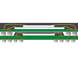
    Amkor's high density package stackable very thin fine pitch BGA (PSvfBGA) bottom package combines the capabilities from well established package technology platforms: thin stacked die capability with low loop wire bonding and etCSP's (Extremely Thin Chip Scale Package) advanced center pin gate molding on four layer (1-2-1) high density laminates to handle the high wiring density and crossing memory circuits. The top overmolded FBGA package with solder balls around the periphery contains the memory chips and surface mounts directly on top of the bottom package straddling the logic chip. The same or similar lead-free alloy solder balls are used on the top and bottom so the stack reflows uniformly during surface mount board assembly. The packages come together during the final assembly process allowing the OEM to control its device integration. Up to that point, there is flexibility to mix and match the top and bottom devices and preferred suppliers as required. The PoP structure is an open platform with JEDEC standards in place for the design guide, mechanical outlines and various memory pin outs across a range of package sizes.

    A key objective in JEDEC and in PoP adoption is defining a flexibly memory interface that supports multiple memory combinations and is supported by all the key memory suppliers as a standard. These standards enable the logic supplier to better floor plan her processor's memory controllers and interconnect interface as a design for stacking which can reduce the package wiring density to reduce cost and improve electrical performance. Current processors are designed for CSPs to interface to a memory Multi-Chip Package (MCP) adjacent on the mother board, as a result the memory interface bond pads are on one side of the chip which pushes wiring density into the bottom logic package to reroute the crossing memory circuits from the top four-sided package

    To deploy PoP stacks in high volume, a key design challenge is controlling warpage of the bottom package across high temperature lead-free solder reflow profiles. As a result, the mold compound for the top and bottom packages are not necessarily the same. Because the bottom package has an unbalanced construction, the compound is specifically selected for warpage control. "When you mold all the way to the package edges and saw singulate like the top MCP, that's much easier to control warpage and coplanarity," says Smith. "With the unbalanced package, the substrate is thicker than the mold cap, so the coefficients of thermal expansion (CTE) and modulus of elasticity of the materials become more important."

    Another key aspect to address warpage was shifting the industry from looking at room temperature coplanarity as the critical criteria for incoming inspection. Since the warpage factors with two packages are most critical at the liquidus temperature where the two units solder together, this changed to characterizing the two packages together for the warpage profile across the reflow temperature profile. This shift in industry thinking has proven to be effective. "Stacking yields are being reported from OEMs at high levels matching what they get with 0.5 mm CSP assembly," notes Smith.

    The first PoP stack for cellphones went into production in October 2004. The PoP stack had four elements in the top package — SDRAM, NOR and NAND die plus a spacer. "When you get to complex four and five stacks with low cumulative die yield and high die and test cost, then PoP overwhelmingly becomes the lowest cost solution," says Smith.

    The outlook for the market acceptance for PoP products is extremely good. Jan Vardeman of market research company TechSearch International forecasts 300 million packaging stacks for 2007. Part of this optimism is based on equipment suppliers either optimizing or retrofitting their equipment for package stacking. "The EMS/OEM guys are quickly coming on board," says Smith. "Flextronics has been doing this in high volume assembly for a couple of years. By next year this will become a dominant technology for logic plus memory integration."

    Contact: Lee Smith, senior director business development, Amkor lsmit@amkor.com

    Saturday, February 10, 2007

    Hermatic Semiconductor

    The present invention is directed to several embodiments of a hermetically sealed semiconductor package. One embodiment is constructed from a substrate of a first copper alloy, a cover member of a second copper alloy and a lead frame of a third copper alloy. A low melting point sealing glass composite is disposed between the cover member and the substrate for sealing the lead frame therebetween. The third copper alloy is precipitation hardenable and has excellent softening resistance at glass sealing temperatures as compared with other conventionally used alloys. In another embodiment, a clad composite having a core of the third copper alloy and cladding layer of a copper alloy having a low oxidation rate may be advantageously used for the lead frame

    Semiconductor Package

    Abstract

    A semiconductor package for mounting a chip is disclosed. The package includes a first metal or metal alloy component having a first thin refractory oxide layer on a first surface. The chip is bonded to the first component. A skirt extends from the first component for strengthening the first component and providing heat transfer from the semiconductor package. A second metal or metal alloy lead frame having second and third refractory oxide layers on opposite surfaces is electrically connected to the chip and is bonded to the first oxide layer. Also, the lead frame is insulated from the first component by the first and second refractory oxide layers. A second metal or metal alloy component has a fourth refractory oxide layer on one surface and is bonded to the third refractory oxide layer so that the chip is hermetically sealed between the first and second components. Other embodiments of the present invention include both leadless and leaded hermetic semiconductor packages...